After opening the controller, you will see how simple the mechanism actually is. Usually there is one switch for the autofocus and one for the shutter trigger. We won’t be using the autofocus switch so all you need to worry about is the shutter trigger switch (you will manually focus the lens).

Image of the internal mechanism of an inexpensive cable switch
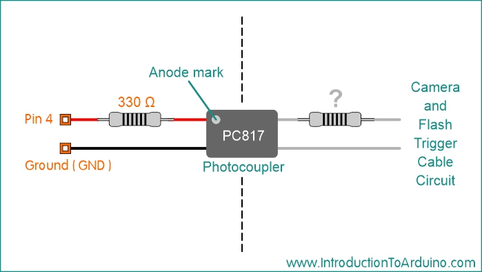
After determining the switch you need to work with you can either solder wires directly to the switch components (then isolate them with electrical tape) or clip the wires and wire the cable directly to your Arduino. If you do wire the cable directly to your Arduino, make sure you include an appropriate resistor in the circuit (if the controller used a resistor). This resistor value can be determined by placing a multimeter at the plug end of the cable and reading the resistance when the switch is closed. Normally the first switch is for autofocus and the second controls the shutter, but each manufacturer may have their own triggering scheme. The only special component you will need is a PC817 Photocoupler. These little components are cheap and they help isolate the camera’s circuit from your Arduino’s circuit. This helps ensure you don’t have power running between the camera and Arduino. What does a Photocoupler do? They are really pretty simple but quite useful; inside the housing is a tiny LED emitter and a photosensor facing each other with a gap between them. When power is applied to the LED side (Arduino side) the LED turns on, when the photosensor facing it sees the light it switches the second circuit on (the camera remote switch circuit in our case). When power is removed from the LED side, the LED turns off and the photosensor shuts off the second circuit. Perfect for situations like our Arduino controlled cable switch project. Photocouplers are directional so you need to make sure you orient them so the tiny Anode indicator marking (small circle) is on the Arduino side of the setup (positive). You will also need to include a resistor so the LED inside the Photocoupler doesn’t burn out.

PC817 Photocoupler showing the location of the Anode mark (circle in the top left corner)
1 330 Ohm Resistor 1 Additional Resistor (if required) 1 Cable with a connector to fit your camera 1 Arduino UNO R3 1 Breadboard Connector Wires
Code:
//------------- Code Starts Here ----------------------------

//-----------------------------------------
//Published by IntroductionToArduino.com
//Created by Paul Illsley (www.paulillsley.com)
//Please use and share so others can enjoy
//-----------------------------------------

// Change this “delay_seconds” value to adjust the time between images (in seconds)
int delay_seconds = 3;

// Naming pin 4 "Trigger"
int Trigger = 4;

void setup() {
  // Declaring pin 4 (Trigger) as an output
  pinMode(Trigger , OUTPUT);

  // Turning off pin 4 (Trigger)
  digitalWrite(Trigger , LOW);
}

void loop() {
  // Turning on pin 4 (Trigger)
  digitalWrite(Trigger , HIGH);

  // Delaying 100 milliseconds
  delay(100);

  // Turning off pin 4 (Trigger)
  digitalWrite(Trigger , LOW);

  // Delaying the “delay_seconds” value and subtracting 100 milliseconds
  // to account for the earlier 100 millisecond delay
  delay((delay_seconds*1000)-100);
}

//------------- Code Stops Here ----------------------------
Return to www.introductiontoarduino.com
|