
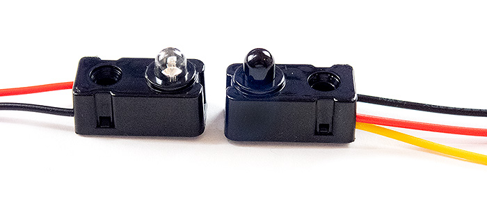
5mm IR Break Beam Sensor Set. Emitter (left), Receiver (right) Wiring: Red (5V Power), Black (Ground), Yellow (Sensor data)
With a few basic parts and the code supplied below you will be able to make a system that automatically triggers your camera when an objects passes through a precise point in space. If you have your camera focused on that point you should be able to record interesting images without any actions on your part. Wiring is quite simple. All you need to do is have the red wires from the sensors connected to power pins of your Arduino (5V), the black wires connected to Ground pins, and the yellow wires (one from each receiver sensor) attached to different pins on the Arduino (Pins 2 and 7 in this case). These 5mm break beam sensors have a maximum range of 50cm so you will need to keep your setup quite compact. I used a 40cm X 40cm frame for this example. The transmitter has a 10° angle of illumination so you need to make sure your receiver falls within this angle of illumination.
NOTE:
Due to the time delay between the camera being triggered and it recording an image (due to the relatively slow shutter response times of most cameras), this system may not be useful for recording images of fast-moving objects. Test its effectiveness for your application before deploying the setup.
To achieve faster image captures you could trigger a flash directly and bypass the camera trigger altogether. Unfortunately, this means you would need to have the shutter remain open for a long period of time while waiting for something to trigger an image which will probably increase the background exposure in your image. You could use a low ISO (100), a small lens aperture like F22 and record images at night with a black background to help decrease this background exposure. This method could also be used in a dark room with all the lights turned off.
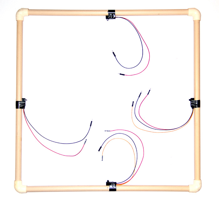
40cm X 40cm Double Break Beam Frame Setup
Attach one emitter and one receiver to opposite sides of the frame (attach the other pair to the remaining sides in a similar fashion). Attach all the RED wires to 5V on the Arduino. Attach all the BLACK wires to Ground on the Arduino. Attach one YELLOW wire to Pin 2 on the Arduino. Attach the other YELLOW wire to Pin 7 on the Arduino. Attach the TRIGGER circuit to Pin 4 on the Arduino. Information about the camera trigger setup is available HERE . Set the delay interval between images to allow the flash to recharge (default is 5 seconds). This setting is in the top part of the code. Upload the supplied code to your Arduino. Test your system to make sure the camera is triggered when both beams are interrupted. You can now turn off your Arduino. Set up your frame and make it as stable as possible. Set up your camera and make sure your area of interest in within the frame. Set your camera to Manual Focus and focus at the approximate position where the two beams cross. You can hold an object at that position to help you focus. Remove the object. Turn your Arduino and Camera on. Test the trigger by moving something through the point where the beams crosses. Check the image and adjust the framing, focus, aperture (for depth of field) and exposure. Make a few test images to ensure the system is working properly. Have fun.
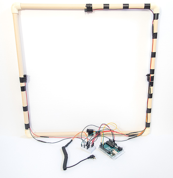
40cm X 40cm Double Break Beam Frame Setup Completed (Camera Trigger Setup)
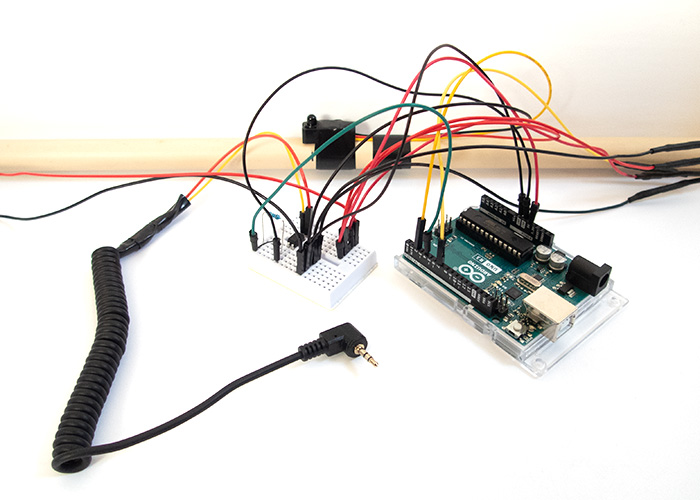
Double Break Beam Controller and Wiring Setup (Camera Trigger Setup)
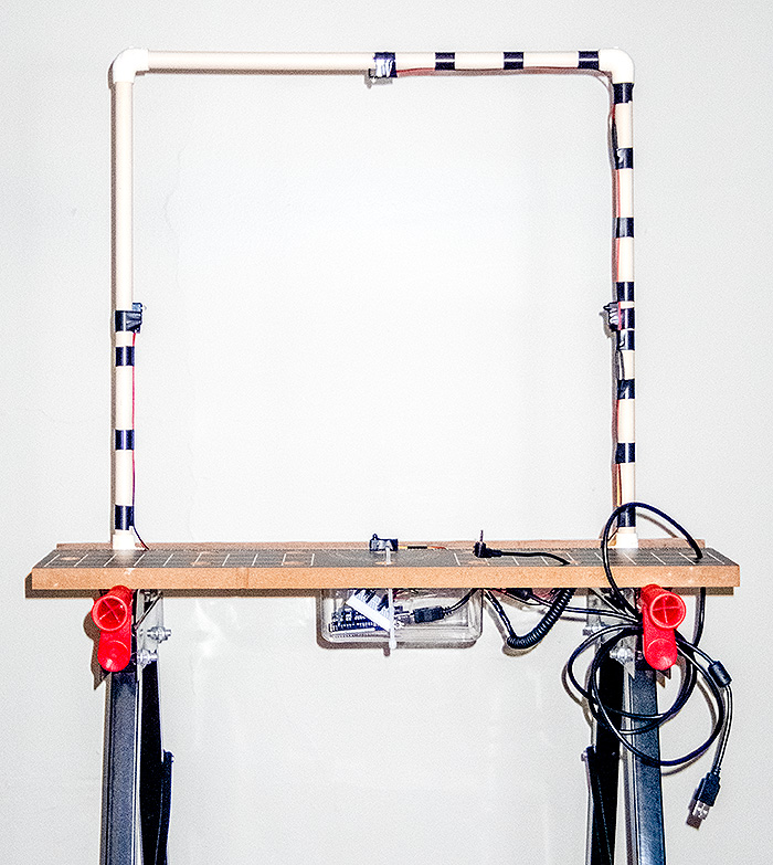
Setup Mounted on a Portable Workbench
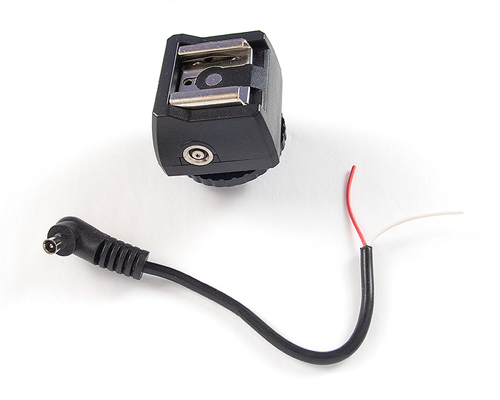
Hot Shoe Adapter with a “Sync Cord” Connector
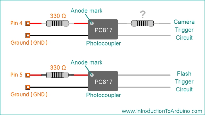
Flash and Camera Trigger Setup (for fast moving objects)
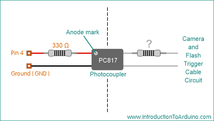
Camera Trigger Setup (flash is triggered by the camera) (for slower moving objects) More information about the camera trigger setup is available HERE .

Flash Trigger Setup In Action Camera shutter open (bulb setting) with the flash being triggered directly More information about the camera trigger setup is available HERE .
4 90 degree corners for 1/2 inch PVC pipe 2 pair of 5mm IR Break Beam Sensors 1 PC817 Photocoupler 1 330 Ohm Resistor 1 Additional Resistor (if required for camera trigger setup) 1 Cable with a connector to fit your camera 1 Arduino UNO R3 (or similar microcontroller) 1 Breadboard Connector Wires Information about the camera trigger setup can be found HERE
Code for Camera Trigger:
//------------- Code Starts Here ----------------------------

//-----------------------------------------
//Published by IntroductionToArduino.com
//Created by Paul Illsley (www.paulillsley.com)
//Please use and share so others can enjoy
//-----------------------------------------

// *** Set the “delay_seconds” value (in seconds) for camera's flash to recharge ***
int delay_seconds = 5;

// Defining pin 7 as Sensor _1
#define Sensor_1 7

// Defining pin 2 as Sensor _2
#define Sensor_2 2

// Defining pin 4 as the camera "Trigger"
#define Trigger 4

// Creating two integer variables, one for each beam
int Beam_1 = 0;
int Beam_2 = 0;

void setup() {

  // Declaring pin 4 (Trigger) as an output
  pinMode(Trigger , OUTPUT);

  // Turning pin 4 (Trigger) off
  digitalWrite(Trigger , LOW);

  // Initialize the sensor pins as an inputs:
  pinMode(Sensor_1, INPUT);
  pinMode(Sensor_2, INPUT);

  // Turning on the pullup resistor for each sensor
  digitalWrite(Sensor_1, HIGH);
  digitalWrite(Sensor_2, HIGH);
}

void loop(){
    // Read the state of both pin values:
    Beam_1 = digitalRead(Sensor_1);
    Beam_2 = digitalRead(Sensor_2);

    // Check to see if both beams are broken (both values are 0)
    if ((Beam_1 == 0) && (Beam_2 == 0)){

    // If both are broken, record an image (Trigger)
    digitalWrite(Trigger , HIGH); // Turning on pin 4 (Trigger)
    delay(100); // Delaying 100 milliseconds
    digitalWrite(Trigger , LOW); // Turning off pin 4 (Trigger)

    // Delay a set period of time (delay_seconds) to let the camera's flash recharge
    delay((delay_seconds*1000)-100);

  }
}

//------------- Code Stops Here ----------------------------
Code for Flash and Camera Trigger Setup:
Return to www.introductiontoarduino.com
|